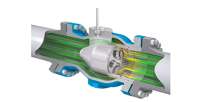
The CV of valves refers to their flow coefficient and provides one of the important parameters when selecting a valve for an application. Moreover, its value quantifies a valve’s ability to pass flow. In this article, you will learn more about CV, how to calculate it, and review a CV valve chart.

More on CV of Valves
CV of a valve is an imperial measure that relates flow rates in gallons per minute (gpm) to pressure drop in psi at a temperature of 60℉. Its value is usually in a valve’s specifications because it is key to engineers and manufacturers in selecting the appropriate size of valve for an application.
The larger the CV value, the more the flow rate through a valve. For example, a CV value of 3 means that 3 gpm will flow through the valve with a pressure drop of 1 psi. Determining the right CV value is important when designing flow systems, as a wrong selection could lead to poor valve performance in a variety of ways.
- Overestimating the CV value leads to selecting an oversized valve that takes up more cost, space, and weight than necessary. Also, it may result in significant throttling and water hammer in control valves.
- On the other hand, underestimating the CV value can cause pressure drop across the valve to be higher than expected. As a result, cavitation, flashing, and starvation for the process fluid may occur. In addition, the valve may not be able to open or close completely, leading to leakages and other hazards.
- Having a valve that is too small or too large increases energy consumption. Moreover, increased wear and tear can shorten the valve lifespan and make maintenance costly. The inconsistent flowrate of the system results in poor performance.
Combining CV Values
In many industrial applications, multiple valves are utilized at the same time to deliver a fluid. When this occurs, engineers use a combined CV value to analyze the flow. This value is estimated based on the configuration of the valves. For a parallel arrangement of valves, the total CV would be as follows:
[Latexpage] \[ C_{v}=C_{v1}+C_{v2}+C_{v3}+… \]
While for a series setup of valves, the aggregate coefficient would be:
[Latexpage] \[ \left ( \frac{1}{C_{v}} \right )^{2}=\left ( \frac{1}{C_{v1}} \right )^{2}+\left ( \frac{1}{C_{v2}} \right )^{2}+\left ( \frac{1}{C_{v3}} \right )^{2}+… \]
How to Calculate Valve CV
To accurately estimate the valve CV requirement for an application, the engineer must take into account:
- The desired flow rate (Q).
- Pressure differential across the valve (ΔP).
- Specific gravity of the fluid (SG).
Although the same parameters apply to both liquids and gasses, their formula for calculating CV are different due to variations in compressibility and viscosity.
Calculating CV of Valves for Liquids
When water, or any liquid is the medium, the valve flow coefficient is expressed as follows.
[Latexpage] \[ C_{v}=Q\sqrt{\frac{SG}{\Delta P}} \]
Calculating CV for Gasses
Calculating CV for gasses is not as straightforward as for liquids. This is due to its viscosity and compressibility changes with temperature (T) and pressure (P). Their effect is integrated into the equation. So, for a given gas, the CV expression varies depending on the relationship between the pressure differential and the upstream pressure (P1). If the pressure differential is less than half of the upstream pressure, then the coefficient is estimated as follows:
[Latexpage] \[ C_{v}=\frac{Q}{963}\sqrt{\frac{SG\times T}{\Delta P\left ( P_{1}+P_{2} \right )}} \]
On the other hand, if the pressure differential is greater than half of the upstream pressure, the following expression will suffice.
[Latexpage] \[ C_{v}=\frac{Q\times \sqrt{SG\times T}}{750P_{1}} \]
For gasses, the flow temperature is in Rankine, pressure in psia, and volumetric flow rate in scfh.
CV Valve Chart
A typical CV valve chart contains a range of CV values for a particular valve. These values change according to the valve type, size, and manufacturer. Another parameter that influences a CV value is the level to which the control valve is open. This is usually expressed in percentage or degrees open as the CV chart for a butterfly valve below shows.
| Valve Size (Inches) | CV Value at Different Degrees of Opening | ||||||||
| 10° | 20° | 30° | 40° | 50° | 60° | 70° | 80° | 90° | |
| 2 | 0.1 | 5 | 12 | 24 | 45 | 64 | 90 | 125 | 135 |
| 2½ | 0.2 | 8 | 20 | 37 | 65 | 98 | 144 | 204 | 220 |
| 3 | 0.3 | 12 | 22 | 39 | 70 | 116 | 183 | 275 | 302 |
| 4 | 0.5 | 17 | 36 | 78 | 139 | 230 | 364 | 546 | 600 |
| 5 | 0.8 | 29 | 61 | 133 | 237 | 392 | 620 | 930 | 1022 |
| 6 | 2 | 45 | 95 | 205 | 366 | 605 | 958 | 1437 | 1579 |
| 8 | 3 | 89 | 188 | 408 | 727 | 1202 | 1903 | 2854 | 3136 |
| 10 | 4 | 151 | 320 | 694 | 1237 | 2047 | 3240 | 4859 | 5340 |
| 12 | 5 | 234 | 495 | 1072 | 1911 | 3162 | 5005 | 7507 | 8250 |
Using charts like these from an OEM, as well as the CV equations from the previous section, flow engineers can easily estimate:
- Pressure drops for a given valve size and flow rate.
- Flow rate range according to valve size.


Recent Comments