High pressure applications are common in the energy industry and require reliable and efficient valve designs. High-pressure valves are important in controlling the flow, direction, and pressure in these systems. However, these tough operating conditions offer unique challenges that necessitate certain considerations in the valve design or selection process. This article delves into the qualifications of high-pressure valves, design considerations, and applications of these valves in the oil and gas industry.
Qualifications of High-Pressure Valves
Generally, high-pressure valves operate at a maximum working pressure of at least 500 psi. However, this classification varies depending on the industry in question. In certain applications, the pressure can get much higher, so each valve must be qualified for its operating environment to ensure reliable and safe service. As such, there are different classifications of high-pressure valves.
Class Ratings
Class ratings refer to the qualification of a valve according to its pressure-temperature rating, where each rating has a designated class number. ASME B16.34 is a common valve standard that provides class ratings indicative of the maximum allowable working pressure at a particular temperature. These ratings range from Class 150 to Class 4500, depending on the type of valve material. Pressure ratings for this standard are expressed as gauge pressures, with an example for Group 1.1 Materials as follows.
| Temperature ℃ | Class 150 | Class 300 | Class 400 | Class 600 | Class 900 | Class 1500 | Class 2500 |
| -29 to 38 | 19.6 | 51.1 | 102.1 | 153.2 | 255.3 | 425.5 | 765.9 |
| 50 | 19.2 | 50.1 | 100.2 | 150.4 | 250.6 | 417.7 | 751.9 |
| 100 | 17.7 | 46.6 | 93.2 | 139.8 | 233.0 | 388.3 | 699.0 |
| 150 | 15.8 | 45.1 | 90.2 | 135.2 | 225.4 | 375.6 | 676.1 |
| 200 | 13.8 | 43.8 | 87.6 | 131.4 | 219.0 | 365.0 | 657.0 |
| 250 | 12.1 | 41.9 | 83.9 | 125.8 | 209.7 | 349.5 | 629.1 |
| 300 | 10.2 | 39.8 | 79.6 | 119.5 | 199.1 | 331.8 | 597.3 |
| 325 | 9.3 | 38.7 | 77.4 | 116.1 | 193.6 | 322.6 | 580.7 |
| 350 | 8.4 | 37.6 | 75.1 | 112.7 | 187.8 | 313.0 | 563.5 |
| 375 | 7.4 | 36.4 | 72.7 | 109.1 | 181.8 | 303.1 | 545.5 |
| 400 | 6.5 | 34.7 | 69.4 | 104.2 | 173.6 | 289.3 | 520.8 |
| 425 | 5.5 | 28.8 | 57.5 | 86.3 | 143.8 | 239.7 | 431.5 |
| 450 | 4.6 | 23.0 | 46.0 | 69.0 | 115.0 | 191.7 | 345.1 |
| 475 | 3.7 | 17.4 | 34.9 | 52.3 | 87.2 | 145.3 | 261.5 |
| 500 | 2.8 | 11.8 | 23.5 | 35.3 | 58.8 | 97.9 | 176.3 |
| 538 | 1.4 | 5.9 | 11.8 | 17.7 | 29.5 | 49.2 | 88.6 |
Cold Working Pressure Rating
Cold working pressure (CWP) rating represents the maximum allowable working pressure between -4 and 212F. Sometimes, this rating is referred to as cold rating or water-oil-gas (WOG) rating, because valves having this rating are usually those serving in water, oil, and gas transmission and distribution systems.
General Service Rating
General service rating is equivalent to the CWP rating. However, manufacturers often assign it alongside a fire rating. For example, a valve could have a general service rating of 400 psig, and have a maximum allowable working pressure of 170 psig in a fire protection system. Another instance of dual rating is when a valve design allows it to comply with more than one standard. As an example, a valve could be a Class 600 under ASME B16.34, while also complying with the API 603 Class 800.
Design Considerations for High-Pressure Valves
The design process for high-pressure valves entails material selection, body design, valve actuation, and flow characteristics.
Material Selection

Choosing the right materials is critical for high-pressure valves to withstand extreme conditions. Materials must exhibit excellent mechanical strength, corrosion resistance, and compatibility with the flow media. Standards such as the ASME B16.34 provide a good reference for selecting valve materials. However, it is common practice to select materials that exceed industry standards with a proven track record of performance. Common high-pressure valve materials include stainless steel, alloy steels, titanium, and other high-performance alloys.
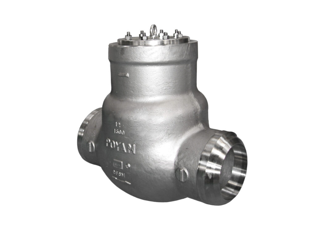
Body Design
Valves can come in a variety of body designs. But for high-pressure valves, bolted bonnet, welded bonnet, and pressure seal configurations are preferable. Threaded connections are generally avoided in high-pressure applications. Welded bonnets offer high reliability, but are difficult to access, so are not ideal for valves that require regular maintenance. Bolted bonnets are the most common as they offer both durability and accessibility. However, the size and weight of the valve increases as operating pressure increases. This could be a restraining factor in very high-pressure applications, where pressure seals are ideal.
Valve Actuation
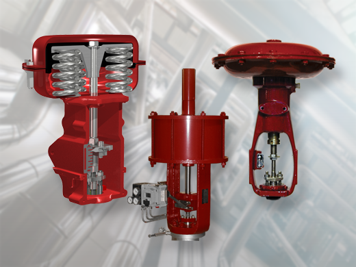
Careful selection of the valve actuation mechanism is necessary because high pressure could make valve operation more difficult. Depending on factors like the type of valve, force/torque requirements, and location of the valve, actuation may be manual, electric, hydraulic, or pneumatic. Manual actuation works well for low pressure applications, when the valve is easily accessible, and not frequently operated. Electric, hydraulic, and pneumatic actuators are ideal where there is limited access to the valve or it is frequently operated. When actuation is over a significant distance such as in subsea valves in the oil and gas industry, electric actuation could prove advantageous because of speed.
Flow Characteristics
The design of high-pressure valves should minimize pressure drops, turbulence, and flow restrictions. Factors such as the valve type, seat design, and trim configurations influence energy loss and flow control accuracy. Generally, the most common high-pressure valve types are gate, globe, ball, and needle valves. Gate and globe valves excel in applications where flow isolation is most important. Whereas needle and globe valves are ideal for flow metering.
High-Pressure Valves in the Oil and Gas Industry
Advances in valve technology have allowed more high-pressure and high-temperature (HP/HT) oil/gas wells to become commercially viable. Although there is a minimum industry-accepted designation of 10,000 psi as HP and 150℃ as HT, these advances enable the industry to push the barriers even further. Some common applications of high-pressure valves in the oil and gas industry are as follows:
- Wellhead Control: Wellheads offer the most rigorous operating conditions in an oil and gas system. So, they require the toughest valves, especially downhole. Valves at the wellhead must be able to completely isolate flow when required, as well as regulate it to ensure safe and efficient production.
- Subsea Applications: Valves for subsea applications are not only subject to internal pressure, they also experience significant external pressure. These valves can be located anywhere from a few hundred to up to a few thousand meters below sea level.
- Pipeline Transportation: Gas products are usually transported over long distances at high pressures. It is important to minimize pressure drops from valves on these lines that may lead to condensation and the onset of corrosion.
- Emergency Shutdown: High pressure valves are vital components of emergency shutdown systems that safeguard personnel, assets, and the environment. In these systems, the design of the valves must enable swift isolation of process equipment to prevent the escalation of an incident. An example is the High Integrity Pressure Protection System (HIPPS).
- Enhanced Oil Recovery: Oil recovery techniques such as steam injection, gas injection, and chemical flooding utilize high-pressure valves. These valves enable precise control over injection rates, pressures, and fluid compositions in maximizing the recovery of hydrocarbon reserves. They are also key components in fracking operations.
Recent Comments