
A swing check valve allows forward flow and blocks the reverse flow. It provides a strong option for uni-directional homogenous flow applications. In this article, you will review a swing check valve diagram, operating principles, types, k-values, installation concerns, and applications.
Swing Check Valve Diagram
The swing check valve consists of a valve body, seat, and disc linked to the hinge. Upon encountering a specified flow rate, the disc rotates to a horizontal position, enabling forward flow. It returns to the valve seat when the flow stops to prevent backflow.
A variety of disc and seat designs exist to ensure compliance with process media characteristics and to meet the requirements of various applications. Typically, a prescribed amount of upstream pressure is required to operate a check valve. Engineers often refer to this minimum pressure as the cracking pressure. Depending on the valve size, check valves require a certain amount of flow rate to achieve stable operation. Therefore they should be sized to determine suitability for the service conditions.
Operating Principles
The swing check valve’s disc and the rocker connect, allowing them to revolve at an angle around the pin shaft. When input pressure to the disc exceeds resistance pressure, fluid flows in the prescribed direction. While the valve opens, the disc separates from its seat and rotates around the pin to a fully open position.
When the flow rate drops the valve disc will rotate back to the closed position. This prevents backward fluid flow.
Types of Swing Check Valves
There are several major types of swing check valves. Broadly grouped, these can be categorized as top-hinged and tilting disc. Each deploy similar operating procedures with the main difference being the way the valve disc is deployed.
Top-hinged
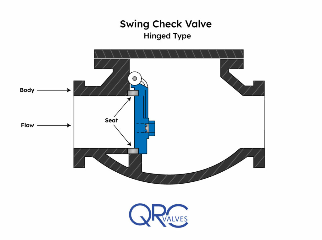
The top-hinged swing check variant is the most common. The disc hinges to the inner top of the valve in this form of swing check valve, thus allowing the disc to open and close. When the disc swings open, it is positioned on the edge of the fully formed turbulent flow profile.
Tilting disc
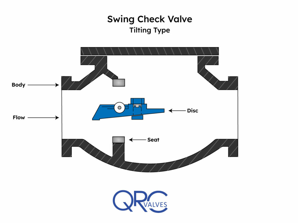
This swing check valve design allows the valve to fully open at lower flow rates and close quicker than a standard swing. Its dome-shaped disc with a central pivot point allows the valve to close faster than a top-hinged one. This quicker closing helps to reduce water hammer during reverse flow conditions. The valve’s disc remains in the flow path after opening.
Swing Check K-Value
The K-value provided by the check value, also known as a K factor or loss coefficient, allows for the calculation of pressure loss through the valve. This applies to a particular fluid, flowing at a specified velocity. Practically, the K-value allows engineers charged with doing process flow calculations to calculate pressure losses.
One of the most common ways to calculate pressure loss is the equivalent loss method via the following formula:
h = K x v² / 2g
where:
h = pressure loss in terms of fluid head
K = manufacturer’s published ‘K’ factor for the valve
v = velocity of fluid
g = acceleration due to gravity
Manufacturers should be able to provide a K value for their products. If not, this dimensionless number can be generated empirically from a Cv value. The Cv number, known as the flow coefficient, may be derived from a chart, table, or be provided by the manufacturer.
A swing check’s K value relates to a given Cv number from any of the following equations:
- K = 894 * D^4 / Cv^2 (D is in inches)
- K = 2.1478E-3 * D^4 / Cv^2 (D is in mm)
- K = 2.1478E+9 * D^4 / Cv^2 (D is in meters)
Installation Concerns
Installation of check valves requires careful attention to the flow direction. Improper installation of a swing check valve can result in catastrophic failure.
Due to the pressure requirements for proper functioning, the most frequent swing check installation is in a horizontal position. The horizontal position provides a simple installation as it eliminates gravity as an additional factor.
Vertical Swing Check Installation
Technicians may install a swing check in the vertical position, although the flow must go upwards. Engineers should generally avoid installation in the vertical position if possible due to gravity impacts.
At times, process conditions may dictate a downward fluid flow. In such situations, a swing check valve should not be used. Gravity will keep the valve continuously open and inadvertent pass-by will occur.
Swing Check valves typically require little maintenance. Visual inspections should occur on a routine basis – with the responsible technician checking for leaks, rust, and debris.
Applications
Swing check valves can regulate and transport water, steam, oil, nitric acid, acetic acid, solid oxidizing medium, and other corrosive media. They usually install in pipelines for petroleum, chemicals, and water-based process flows. They suit clean fluid, not solid-particle-laden or viscosity-intensive media.
Swing check valves are a standard solution in a variety of industries. Power plants, gas transmission, and refineries frequently employ swing check valves. Swing check valves help prevent the improper flow of gas that could result in dangerous leaks or fires. These valves see broad usage in gas pipelines – both in natural gas cleaning, distribution, and compression.
Since swing check valves work well with large, predictable flow, they are frequently used in wastewater treatment and water pumping.
Generally, for clean process media, swing check valves offer good service.
For transporting heavier crudes, distillates, and viscous and heterogeneous material, a spring check valve offers better service than swing check valves. Additionally, intermittent flow can lead to a potential water hammer in the swing check valve. As a result, engineers typically prefer spring check valves for these applications.
Custom Solutions
Swing check valves provide a robust and underrated solution for proper process media control. Sometimes specific applications require a unique modification or entirely original design to solve a challenging flow issue.
Examples include air cushions to reduce slamming effects, changing the angle of the valve, or decreasing the disc’s weight.
QRC Valves offers high-quality DSI Cast, Newco forged, and Poyam stainless valves. Please reach out to the QRC Valves team for technical support on choosing the right valve for your application.
Recent Comments