API 594 is an industry-standard for check valves with widespread application, especially in the petrochemical and oil & gas industries. The standard ensures that the design, manufacture, testing, and inspection of these valves meet requirements for safety, reliability, and performance. This article reviews key elements of API 594 including fitness for service, applicability to check valves, and the different types.
API 594 Applicability to Check Valves
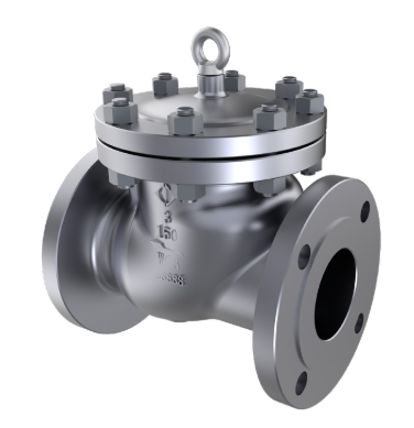
The API 594 is applicable to check valves, which are designed to prevent backflow in piping systems by ensuring unidirectional flow and protection of equipment from potential damage from reverse flow. This standard classifies check valves into two types, which are Type A and Type B.
Type A Check Valve
Type A check valves refer to those with short face-to-face dimensions according to descriptions from Table 2 in the standard. Other features of a Type A check valve include:
- The body pattern may be a wafer, wafer with lugs, or double-flanged.
- The valve disc or obturator may be a single or dual plate, swing disc, or pivoting disc.
- Body materials such as gray and ductile irons and materials in ASME 16.34.
The short face-to-face dimension makes these valves compact and lightweight, hence, suitable in applications where space and weight are critical. This compact design reduces installation space and weight, leading to cost savings in material and installation, thus making Type A check valves common where frequent maintenance and space constraints are common.
Type B Check Valves
Type B check valves are long patterns or short patterns with face-to-face/end-to-end dimensions per ASME B16.10. Other features of this type of check valve include:
- The body may be flanged or have butt-welding ends.
- Obturator may be a swing disc or pivoting disc.
- Body materials as per ASME B16.24.
Because of the longer face-to-face dimensions of Type B check valves, they often resemble gate or globe valves. Moreover, this design provides better mechanical strength and durability in comparison to Type A check valves, making Type B the ideal choice in more demanding environments such as high-pressure and high-temperature applications.
This standard does not cover other types of check valves such as axial disc valves, nozzle-type valves, and lift-type valves.
API 594 Fitness for Service
Fitness for Service (FFS) in the context of API 594 refers to key elements that influence the ability of check valves to perform their function effectively under specified operating conditions. This encompasses several critical aspects, as the following sections highlight.
Design and Construction
API 594 sets rigorous design criteria governing various aspects of the check valve construction like the body, bonnet, end connections, etc.
Valve Body Requirements
API 594 recommends the minimum body wall thickness for both Type A and Type B check valves. Valve designers are at liberty to introduce additional wall thickness after carrying out hydrostatic testing or Finite Element Analysis (FEA). Conditions that may necessitate additional wall thickness include bolt loads, pipe stresses, corrosion, irregular geometries, fatigue, or high-temperature creep.
Wall Thickness
For Type A valves, minimum wall thickness for gray iron is in Table 1 for Class 125 and Class 250 only. Those for ductile iron are also in Table 1 for Class 150 and Class 300 only. Below is a snippet of this table.
| Valve Size DN (NPS) | Class 125 | Class 250 | Class 150 | Class 300 |
| 50 (2) | 6.9 (0.27) | 9.9 (0.39) | 8.6 (0.34) | 9.7 (0.38) |
| 100 (4) | 10.9 (0.43) | 13.7 (0.54) | 11.2 (0.44) | 12.7 (0.50) |
| 200 (8) | 13.7 (0.54) | 18.0 (0.71) | 12.7 (0.50) | 17.5 (0.69) |
| 300 (12) | 18.0 (0.71) | 22.4 (0.88) | 16.0 (0.63) | 20.6 (0.81) |
| 400 (16) | 22.4 (0.88) | 27.7 (1.09) | 17.5 (0.69) | 23.9 (0.94) |
| 500 (20) | 24.9 (0.98) | 33.3 (1.31) | 19.1 (0.75) | 26.9 (1.06) |
| 600 (24) | 27.7 (1.09) | 36.1 (1.42) | 20.6 (0.81) | 30.2 (1.19) |
| 750 (30) | 32.0 (1.26) | 44.5 (1.75) | 23.0 (0.91) | 34.9 (1.37) |
| 900 (36) | 36.1 (1.42) | 52.8 (2.08) | 25.4 (1.00) | 39.96 (1.56) |
| 1200 (48) | 44.4 (1.75) | 69.3 (2.73) | 30.2 (1.19) | 49.5 (1.95) |
For other Type A valve materials, as well as Type B valves, the recommendations are as follows:
- Minimum wall thickness shall be as per API 594-Table 1 for materials in ASME B16.34-Table 1-Group 1.
- For materials in ASME B16.34-Table 1-Group 2 or Group 3, the minimum wall thickness shall be as per requirements of ASME B16.34.
- The wall thickness for materials not covered in ASME B16.34 shall be as agreed between the purchaser and manufacturer.
Face-to-Face Dimensions
Apart from the wall thickness, other key elements in API 594 when dealing with the valve body include the face-to-face dimensions. This is because standardizing this dimension ensures interchangeability and compatibility of check valves with existing piping systems. The requirements for these dimensions are as follows:
- Face-to-face dimensions for Type A valves shall conform to requirements in Table 2 and Table 3. Table 3 serves as an alternative to Table 2 for double-flanged valves to allow clearance for fastener assembly if necessary.
- The face-to-face dimensions for Type B valves shall conform to ASME B16.10 long pattern.
- Special lengths can serve for both Type A and Type B valves only if there is an agreement between the purchaser and manufacturer.
Below are snippets of Table 2 and Table 3.
Table 2
| Valve Size DN (NPS) | Class 125 | Class 250 | Class 150 | Class 300 | Class 600 | Class 900 | Class 1500 | Class 2500 |
| 50 (2) | 54 (2.12) | 54 (2.12) | 60 (2.38) | 60 (2.38) | 60 (2.38) | 70 (2.75) | 70 (2.75) | 70 (2.75) |
| 100 (4) | 67 (2.62) | 67 (2.62) | 73 (2.88) | 73 (2.88) | 79 (3.12) | 102 (4.00) | 102 (4.00) | 105 (4.12) |
| 200 (8) | 127 (5.00) | 127 (5.00) | 127 (5.00) | 127 (5.00) | 165 (6.50) | 206 (8.12) | 206 (8.12) | 206 (8.12) |
| 300 (12) | 181 (7.12) | 181 (7.12) | 181 (7.12) | 181 (7.12) | 229 (9.00) | 292 (11.50) | 305 (12.00) | 305 (12.00) |
Table 3
| Valve Size DN (NPS) | Class 150 | Class 300 | Class 600 | Class 900 | Class 1500 | Class 2500 |
| 50 (2) | 114 (4.50) | 114 (4.50) | 121 (4.75) | 165 (6.50) | 165 (6.50) | 225 (8.87) |
| 80 (3) | 121 (4.75) | 121 (4.75) | 143 (5.63) | 165 (6.50) | 207 (8.12) | 280 (11.00) |
| 100 (4) | 121 (4.75) | 121 (4.75) | 165 (6.50) | 197 (7.75) | 225 (8.87) | 330 (13.00) |
| 150 (6) | 130 (5.12) | 130 (5.12) | 194 (7.63) | 219 (8.63) | 292 (11.37) | 454 (17.87) |
Body-to-Bonnet Joint Requirements
The standard specifies the type of flange joints to use for Class 150 body-to-bonnet connection, which includes:
- Flat face.
- Raised face.
- Tongue and groove.
- Ring joint.
- Spigot and recess.
The standard permits only class 150 valves to have gaskets extend beyond the inner edge of the bolt holes.
Also, the flange joints of Type B valves are to have a minimum of four through-type bolts of at least the following sizes:
- M10 or ⅜ in when 50 ≤ DN ≤ 65 (2 ≤ NPS ≤ 21 /2).
- M12 or 1 / 2 in. when 80 ≤ DN ≤ 200 (3 ≤ NPS ≤ 8).
- M16 or 5 / 8 in. when DN ≥ 250 (NPS ≥ 10).
However, if the purchaser specifies a pressure seal bonnet design, then the previous recommendations do not apply. Rather, the joint construction shall be in accordance with MSS SP-144 Style B unless the purchaser specifies otherwise.
Other key elements of the valve design and their recommendations in API 594 are as follows:
- Plates and Discs: If a nut secures the disc/plate to the hinge arm, it shall be positively secured. Filet welds, lock nuts, or lock washers are not acceptable means of positively securing the nut. Also, the disc assembly shall not limit the disc rotation to less than 360°.
- Seating Surfaces: The construction of seating surfaces may be integral or deposited weld material with a minimum finished thickness of 0.06 in. It could also be of coatings like mechanically-retained metal or resilient material.
Key Elements of API 594 Material
API 594 covers the material requirements for check valve parts with a few of them in the following sections.
Body
Material should conform to purchaser-selected specifications in the applicable ASME standard.
Plate and Disc
The plate/disc shall have corrosion resistance that is at least equivalent to the body material.
Cover Gasket
The cover flange gasket, which is common in Type B valves, shall be of one of the following:
- Solid metal, corrugated, or grooved metal gasket with graphite facing.
- Metal ring joint.
- A spiral-wound metal gasket with filler and a central compression ring are used to provide gasket compression control.
Springs
Unless the purchaser specifies otherwise, spring material shall be:
- Nickel-chromium alloy UNS N07750 for valves operating at 600℉ or above.
- The manufacturer’s standard for valves operating below 600℉.
Inspection, Testing, and Repair
The inspection and testing of API 594 valves shall be in accordance with API 598. This standard requires check valves to undergo shell tests and high-pressure or low-pressure closure tests.
API 594 Shell Test
The shell test entails pressurizing inside the valve assembly with the valve ends shut, the valve partially open, and packing glands tight enough to maintain test pressure. The table below lists the requirements for this test for check valves according to API 598.
| Valve Type | Shell Test Pressure (PSI) |
| Ductile Iron Class 150 | 400 |
| Ductile Iron Class 300 | 975 |
| Cast Iron Class 125 (NPS 2 – 12) | 350 |
| Cast Iron Class 125 (NPS 14 – 24) | 265 |
| Cast Iron Class 250 (NPS 2 – 12) | 875 |
| Cast Iron Class 250 (NPS 14 – 24) | 525 |
| Flange and Butt-Weld Steel Class 150 – 2500 | Per ASME B16.34 |
| Screwed and Socket-Weld Steel Class 800 | 150% valve pressure rating at 100℉ rounded off to the next higher increment of 25 psi. |
Closure Test of API 594 Check Valves
For high- or low-pressure closure tests, the sealing surfaces need to be clean and free from oil, grease, and sealant. If necessary, to prevent galling, coat the sealing surfaces with a film of oil that is not heavier than kerosene. Note that this requirement does not apply to valves using lubricant as their primary seal. The pressure requirements for high-pressure and low-pressure closure tests for check valves as per API 598 are as follows.
| Valve Type | Test Pressure (PSI) |
| High-Pressure Closure | |
| Cast Iron Class 125 (NPS 2 – 12) | 200 |
| Cast Iron Class 125 (NPS 14 – 48) | 150 |
| Cast Iron Class 250 (NPS 2 – 12) | 500 |
| Cast Iron Class 250 (NPS 14 – 48) | 300 |
| Ductile Iron Class 150 | 250 |
| Ductile Iron Class 300 | 640 |
| Carbon steel, stainless steel, and alloys | 110% of maximum allowable pressure at 100℉. |
| Low-pressure closure | 60 – 100 |
Test Duration
| Valve Size (NPS) | Shell Test (s) | Closure Test (s) |
| ≤ 2 | 60 | 60 |
| 2½ – 6 | 60 | 60 |
| 8 – 12 | 60 | 60 |
| 14 ≤ | 120 | 120 |
How to Purchase the Right API 594 Check Valve
API 594 covers much more detail beyond the scope of this article. Purchasing the right valve for your application requires a thorough understanding of the standard and operating conditions. Our team at QRC offers expert consultation based on decades of experience to simplify this selection process. We also offer customized and standard check valve options from reputable manufacturers, such as Cameron’s NEWCO and L&T valves.