A blowdown valve’s main function is to control a continuous or intermittent flow of steam or fluid under high differential pressure. When installed in a system, they drain solid contaminants from the fluid. In this article, you will learn the working principle of a blowdown valve, review a blowdown valve diagram, and its use in boiler and compressor applications.
Working Principle of Blowdown Valves
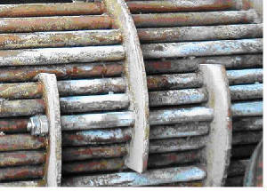
In industry, blowdown valves often attach to equipment where water is the working fluid. Usually, this water contains suspended solid impurities. As mechanisms such as vaporization or drafting occur in the system, the concentration of undissolved solids increases and hampers system performance. How? Some of these deposits may accumulate and form blockages that disrupt the flow. Also, the solids could deposit on the surface of the equipment and impact heat transfer. This reduces the efficiency of heat exchangers and designed cooling measures. Thus, blowdown valves along drain lines allow for the removal of these contaminants.
It is a common practice to use two blowdown valves in series. One acts as the seal valve, while the other is the main blowdown valve. Customarily, the seal valve opens first when draining, and closes last. However, to minimize erosion of the valve disk faces and seats, both may open simultaneously and rapidly.
In addition, care should be taken to avoid trapping scale and rust particles within the valve by briefly reopening it, after it has been shut. Especially if there was resistance when closing it initially. One important parameter in the operation of blowdown valves is the blowdown percentage. It refers to the ratio of the quantity of blowdown water (Vblowdown) to that of the feedwater (Vfeed) as the formula below shows.
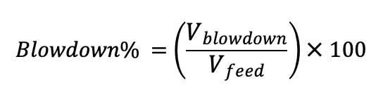
For most applications, the blowdown percentage lies between 4% to 10%. However, it could be as low as 1% when the system has access to high-quality feedwater. On the other hand, it could reach above 20% in a critical system with poor quality feedwater. In any case, caution should be exercised to evacuate as many contaminants as possible, but without emptying the equipment.
Types of Blowdown Valve
The classification of blowdown valves depends on either the valve location or working interval. Generally, blowdown valves are installed at the surface or the bottom of the equipment, depending on the speed of solid impurities precipitation. Also, the valve may operate continuously or intermittently. Usually, surface blowdown valves operate in steady state, while bottom blowdown valves work intermittently.
Surface/Continuous Blowdown Valve
This is suitable for applications where the rate of solid impurities precipitation is relatively slower. For a simple design of this type of valve, a pipe inserts near the surface of the water level. Then, water, along with impurities, goes through the pipe continuously as the valve is normally in the open position.
On the other hand, a more sophisticated design uses a swivel joint with a short length of pipe suspended on a float. Thus, it removes oil floating on the water surface. Typically, surface blowdown valves find use in equipment where a significant amount of vaporization exists. This is because as vaporization occurs, the contaminants, precipitate and remain on the water surface. Also, the outlet of these valves often feeds into a flash tank and provides heating for heat exchangers.
Bottom/Intermittent Blowdown Valve
As the name implies, this type of blowdown valves installs at the bottom of the equipment. They are opened periodically to enable the evacuation of accumulated solid impurities and sludge. Unlike the surface blowdown valve, this type does not operate in a steady state. This is because prolonged opening decreases the water level quickly, thereby risking a shutdown of the equipment. A basic requirement of this valve is to provide tight shut-off even after repetitive blowdown operations. Also, the drainpipe diameter should be large enough so that the slug does not clog and block the flow.
Review of a Blowdown Valve Diagram
Several types of valves can be used to achieve blowdown, but a throttle valve meets all specifications. Some of these requirements include:
- Effective handling of elevated temperatures and pressures.
- Robustness against erosion and corrosion.
- Delivery of consistent shut-off, especially for bottom blowdown valves.
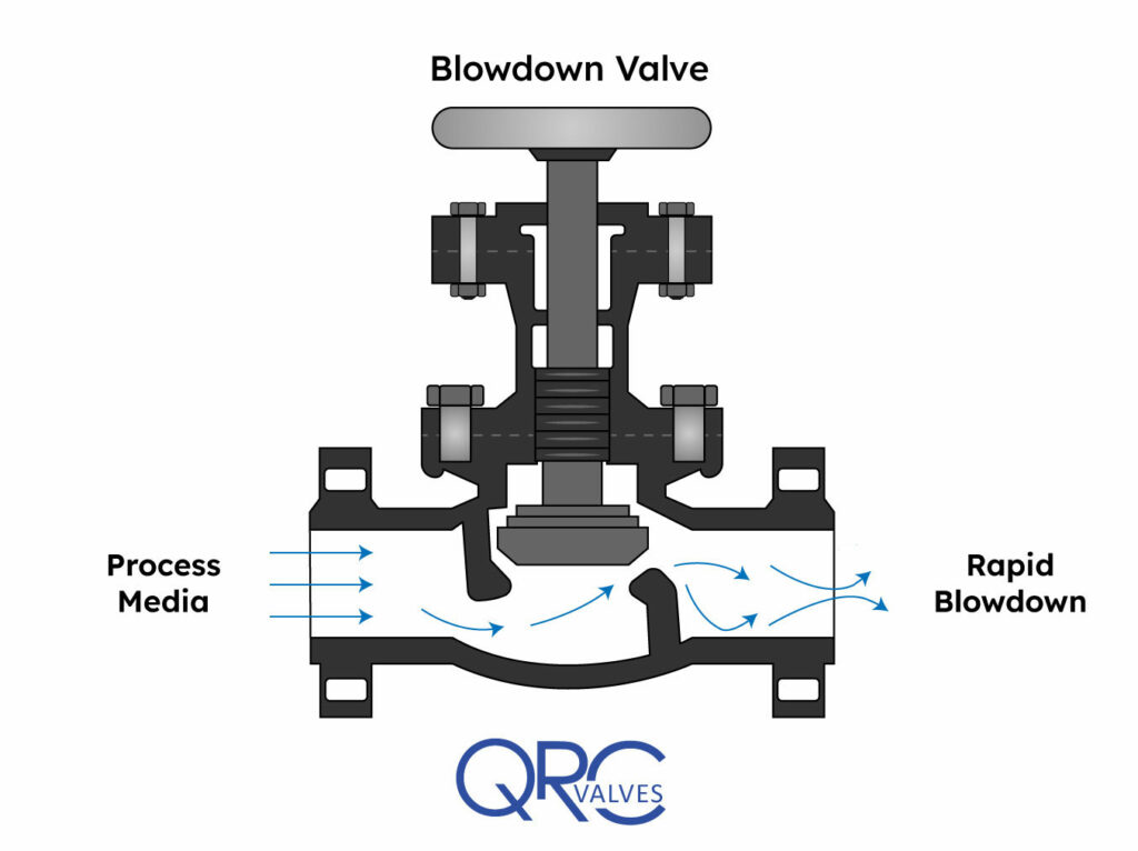
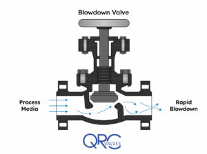
Blowdown Valve (Courtesy: Powermag)
The diagram above is that of a manually operated blowdown valve. Of importance, the orifice maintains fluid velocity below levels that could damage the trim. Also, the stem mates to the orifice for proper control, while the open yoke enables the operator to see the position of the plunger in the valve body. A long stroke length of the stem enables the prevention of water hammer, which occurs if the valve is opened or closed too quickly. At the exit, the angle of the orifice is intentionally made divergent, to minimize downstream piping erosion and noise.
Application in Boilers and Compressors
Blowdown valves are common in boiler and compressor systems. In compressors, they serve to depressurize the gas in the system at critical times such as shutdown, restart, or in the case of an emergency. In boilers, they see more frequent use, where there could be both bottom blowdown valves, and a surface valve, in some cases.
Generally, in boilers, blowdown valves remove both suspended solids and sludge from the surface and bottom respectively. As a result, it prevents the foaming at the water surface which leads to unstable water levels and excessive passing on of liquid in the steam. When blowdown water leaves a boiler, it does so at high temperatures, creating a safety concern. For example, a boiler working at 100 psig typically discharges around 338 ℉. Thus, engineers must ensure controlled discharge occurs into a flash tank prior to disposal into drainage. Or, engineers may repurpose the heat elsewhere within the facility, perhaps to increase feedwater temperature.
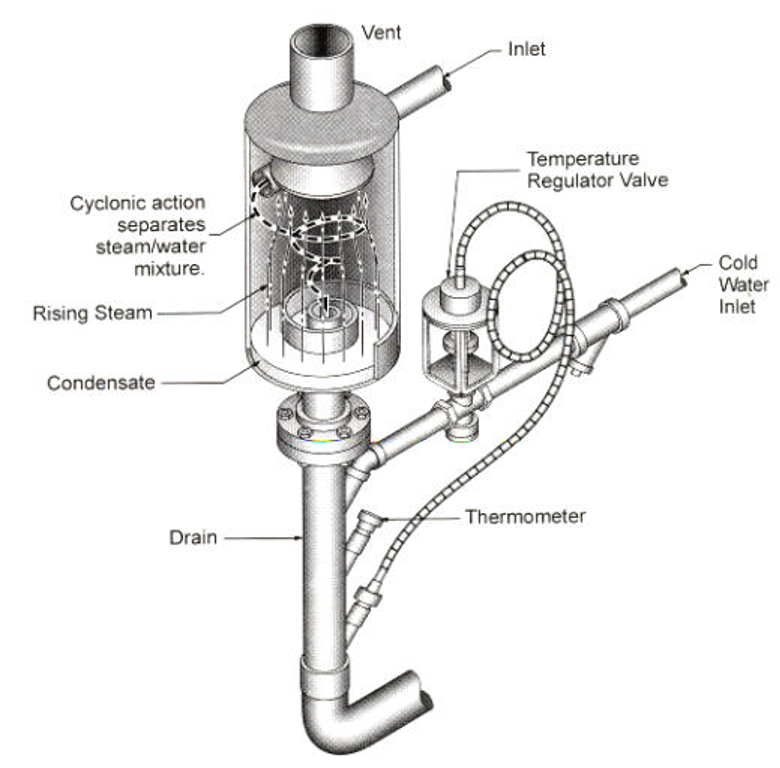
In some cases, having just the flash tank is not enough. Especially if the blowdown will end up in a sewer system. Environmental regulations require that water comes into sewers at 140 ℉ or less. As a result, such facilities use a blowdown separator to separate steam from the liquid, and further cool down the temperature, as seen in the apparatus below.
Recent Comments