Valve trim refers to the operating parts of a valve that are usually exposed to the process fluid. In this article, you will learn more about the meaning of valve trim, review a valve trim chart, learn about the material selection process, and review the selection process in action by comparing two common trims: trim 5 vs. trim 8.
What is Valve Trim?
The trim, particularly the mating elements that regulate the stream to the controller’s demands, is at the heart of the control valve. Each process is distinct in its own right, necessitating particular flow control features. Valve trim includes the stem, plug, disc, seating surface, etc. It’s also the plug and seat arrangement’s actual shape. The flow properties of the valve are determined by the shape of the valve plug.
Valve Trim Plug Characteristics
Shaping the valve trim changes the operating characterization of the valve itself. For example, a stem-guided globe valve’s plug profiles can be specified to be either quick-opening, linear, or equal-percentage.
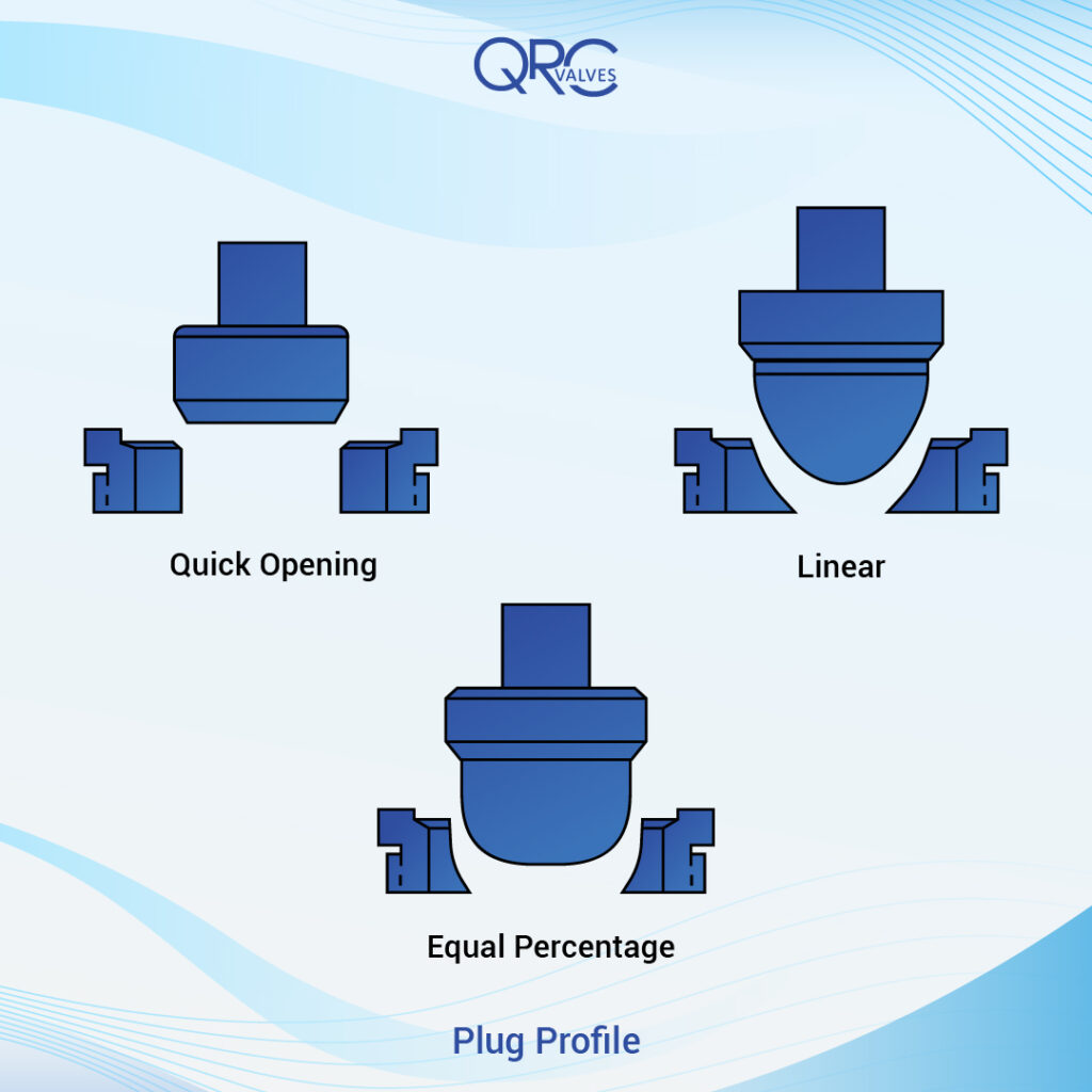
Quick Open
A quick opening valve plug significantly increases flow with a minor initial change in stem travel. Thus, a modest percentage of stem lift achieves near maximum flow. Quick open plugs can quickly create full flow for on-off applications.
Linear
Regardless of plug position, the linear profile delivers step-wise identical changes in flow per unit of valve stroke. Linear plugs are used in systems where the valve pressure drop is a significant fraction of the total system pressure drop.
Equal Percentage
The equal percentage valve plug generates the exact percent change in flow per fixed increment of valve stroke at any point along its characteristic curve. This type of valve trim sees frequent use in high specification applications.
The valve’s flow characteristic curve describes the relationship between valve stem position and flow rate through a control valve. The curve plots the valve opening percentage vs. the maximum flow coefficient (CV). This is established by monitoring the flow rate at several points along the valve’s passage while maintaining a constant differential pressure across the valve. A variant of the generalized Control Valve CV equation computes the CV value at each valve position.
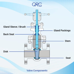
Valve Trim Parts

The valve trim parts are usually made by a lathe machine and they include the back seat, glands, spacers, guides, bushings, retention pins, and internal springs.
Disc
A disc is the initial valve trim component. The disc is the component that, depending on its position, enables, throttles, or stops the fluid flow. The name of the valve often originates from the type of disc. Examples include gate, ball, plug, and needle valves, which have discs that are the same shape as the name.
A valve disc can be forged, cast, or manufactured. The sealing face of the valve disc is occasionally hardened to improve wear resistance. The disc required a smooth machine surface to reduce friction with a seat; the valve disc is a pressure-maintenance component.
In the closed position, a disc rests against the stationary valve seat. The stem may move via manual or automated actuation.
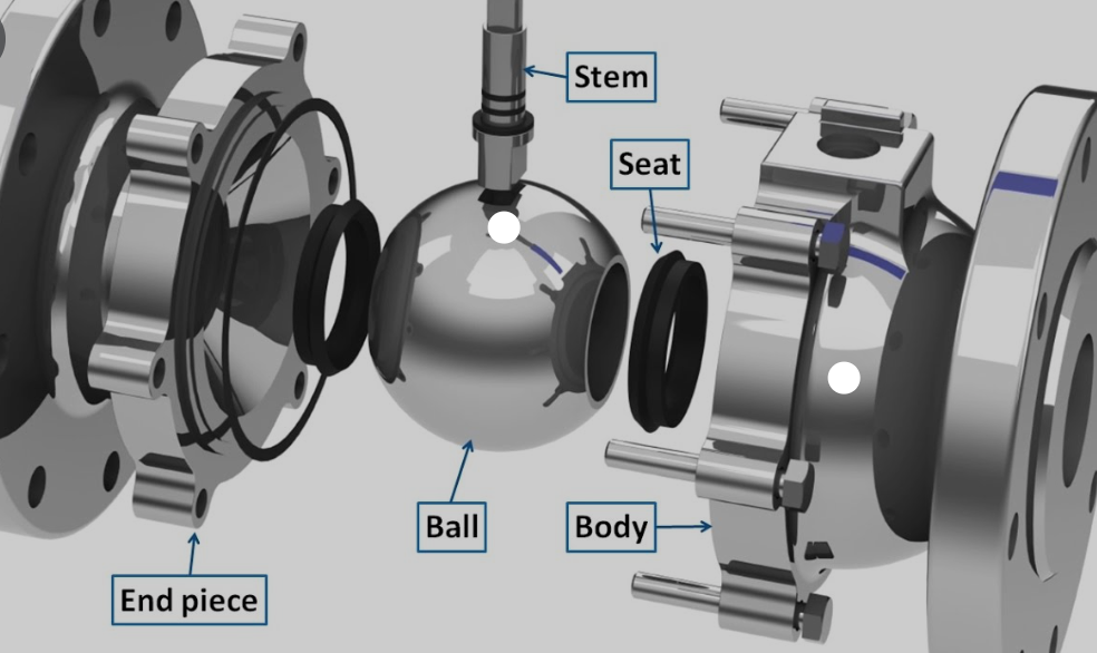
Seat
The seat provides the disc with a place to set and seal against. A valve may have more than one seat. There is only one seat on a globe valve and a swing-check valve. A gate valve and a ball valve, on the other hand, have two seats, one upstream and the other downstream.
The efficiency of the seal between the valve disc and seat is directly proportional to the seat leakage rate. Valve seats can be permanent or removable rings. Seats on valves are often screwed, welded, or integrally cast or forged, and are toughened through heat treatment or hard facing.
For optimal sealing, the seating area must have a fine surface polish. For non-critical applications, non-metallic seats were utilized in some ball valves and plug valves. Valve manufacturers produce numerous styles of combination valve seats that combine elastomer and metal seats to attain the requisite leak tightness that metal seats alone cannot achieve.
Back Seat
The back seat comprises a shoulder on the stem and a mating surface on the underside of the bonnet. When the stem is entirely open, it forms a seal. It inhibits media leakage into the packing chamber and into the environment. Note: For safety reasons, it is NEVER recommended to change the packing while the valve is under pressure.
Stem
The stem links the handwheel/actuator and the disc. The valve disc moves and positions from the stem movement. The valve stem delivers the required motion to the disc, plug, or ball for the valve’s opening, closing, or setting. The stem connects the valve’s actuator, handwheel, or lever at one end to the disc at the other.
The linear motion of the disc opens or closes the valve in gate and globe valves, whereas the disc rotates to open or close the valve in the plug, ball, and butterfly valves. Stems are typically stainless steel and typically attach to the disc via connections or other mechanical means.
Valve Trim Chart
Trim materials such as discs, seats, stems, back sheets, and sleeves are grouped together and assigned one number called trim number or combination number. This defines the material grade for each component.
This system, provided by API, allows for a range from 1 to 18.
| API Trim No. | Material | Seat | Disc | Backseat | Stem | Notes |
| 1 | 410 | 410 | 410 | 410 | 410 | |
| 2 | 304 | 304 | 304 | 304 | 304 | |
| 3 | F310 | 310 | 310 | 310 | 310 | |
| 4 | Hard 410 | Hard 410 | 410 | 410 | 410 | Seas 750 BHN min. |
| 5 | Hardfaced | Stellite | Stellite | 410 | 410 | |
| 5A | Hardfaced | Ni-Cr | Ni-Cr | 410 | 410 | |
| 6 | 410 and Cu-Ni | Cu-Ni | Cu-Ni | 410 | 410 | |
| 7 | 410 and Hard 410 | Hard 410 | Hard 410 | 410 | 410 | Seas 750 BHN min. |
| 8 | 410 and Hardfaced | Stellite | 410 | 410 | 410 | |
| 8A | 410 and Hardfaced | Ni-Cr | 410 | 410 | 410 | |
| 9 | Monel | Monel | Monel | Monel | Monel | |
| 10 | 316 | 316 | 316 | 316 | 316 | |
| 11 | Monel and Hardfaced | Stellite | Monel | Monel | Monel | |
| 12 | 316 and Hardfaced | Stellite | 316 | 316 | 316 | |
| 13 | Alloy 20 | Alloy 20 | Alloy 20 | Alloy 20 | Alloy 20 | |
| 14 | Alloy 20 and Hardfaced | Stellite | Alloy 20 | Alloy 20 | Alloy 20 | |
| 15 | 304 and Hardfaced | Stellite | Stellite | 304 | 304 | |
| 16 | 316 and Hardfaced | Stellite | Stellite | 316 | 316 | |
| 17 | 347 and Hardfaced | Stellite | Stellite | 347 | 347 | |
| 18 | Alloy 20 and Hardfaced | Stellite | Stellite | Alloy 20 | Alloy 20 |
Material Selection Process
Understanding the material selection process is critical to engineering any application and/or part design. All valve applications are built on the foundation of material selection.
Trim Material Selection
The most economical trim material is stainless steel. Available in different grades, this material provides strong resistance to erosive, corrosive, and temperature impacts and provides an excellent all-around choice.
In addition to stainless steel, more expensive materials such as Monel, Alloy 20, and Cu-Ni may be selected. These materials, sometimes referred to as exotic materials, generally are more expensive and have longer lead times than stainless.
Manufacturers’ guidelines should be followed for trim selection. One must consider trade-offs between the initial cost and the estimated service life. For instance, it may be a poor decision to select Stellite trim if it extends the valve’s service life by 20% but doubles the price. It’s essential to think about reliability, downtime, and labor costs.
Applications engineers should not try to correlate operating pressures to anticipated wear.
Hardened Trim
Hardened trim suits most high-pressure applications. Although solid hard plugs are more cost-effective for valves under 1 inch in diameter, a hard material overlay is more cost-effective for larger sizes. These overlays work well for services such as superheated steam, two-phase flow, and high temperatures over 600°F (315°C).
Example of Trim Selection Criteria
Usually, a few front-runners emerge in the trim material selection. For example, two similar trims are Trim 5 and Trim 8 which may be paired against each other. To determine which is the best choice, compare the characteristics of each trim number.
| Details | Trim No. 5 | Trim No. 8 |
| Nominal Trim | 410 – Full Hard faced | 410 and Ni-Cu |
| Trim Code | F6HF | F6HFS |
| Stem and other trim parts | 410 (13Cr) (200-275 HBN) | 410 (13Cr) (200-275 HBN) |
| Disc/Wedge | F6+St Gr6 (CoCr Alloy) (350 HBN min) | Monel 400® (NiCu Alloy) (250 HBN min) |
| Seat Surface | 410+St Gr6 (CoCr Alloy) (350 HBN min) | Monel 400® (NiCu Alloy) (175 HBN min) |
| Trim Material Grade | 13Cr-0.5Ni-1Mn/Co-Cr-A | 13Cr-0.5Ni-1Mn/Ni-Cu |
Trim number 5 provides strong service in high pressure, slightly erosive, and corrosive service between -265°C and 650°C. It is a great fit for high-pressure water and steam service. Trim number 8 provides long service life up to 593°C. It suits moderate pressure applications and corrosive conditions. Generally, trim 5 is considered superior due to the higher degree of hardening.
In this example, determining whether trim 5 vs. trim 8 is the best fit is a matter of understanding the service conditions, but also an exercise in product availability and calculating both the initial capital investment and expected service life. This exercise holds true for all valve trims and all service conditions.
Need help? Feel free to reach out to the QRC Valves team for technical support.
Recent Comments