
Fugitive emission valves have been qualified according to industry standards against the leakage or unintentional release of vapor or gasses. The use of this type of valve is necessitated by environmental regulations and the type of medium transported in the system. In this article, you will learn more about fugitive emissions, fugitive emission valves, as well as the associated valve testing.
Fugitive Emissions
Fugitive emissions refer to the accidental and undesirable release of vapor or gasses from pressure-retaining equipment. This can come from a variety of equipment such as valves, storage tanks, pumps, and other processing equipment. Because these leakages are undetected and unaccounted for, they are detrimental in a variety of ways including:
- Environmental damage from air pollution and greenhouse effects.
- Economic losses due to material waste.
- Health risk to workers and the immediate community if the effluence is hazardous.
- Possibility of fire outbreak and explosions if the gasses are flammable.
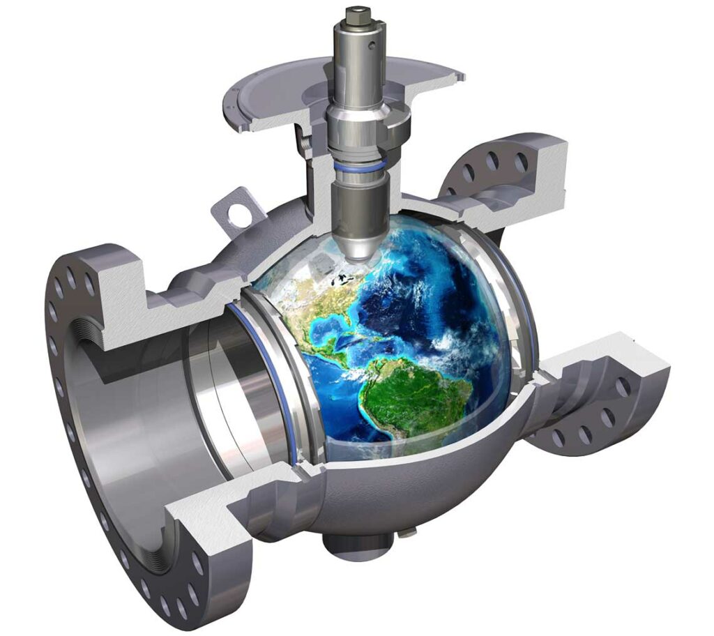
Fugitive Emission Valves
Preventing unwanted emissions has become increasingly important to facilities as its detrimental effects are apparent. Statistics show that about 60% of fugitive emissions come from valves, and up to 80% of these leakages are from its stem-seal interface. Therefore valves are a key concern and play a vital role in preventing fugitive emissions.
A large chunk of this leakage, about 75% comes from pipeline valves, especially control valves. Less frequently operated valves such as relief valves contribute roughly 10% of these valve emissions. The responsibility of preventing leakages often falls on manufacturers who deploy sophisticated technologies and carry out testing of valves. Although the EPA regards bellow seal valves as ideal with zero emissions, they are not cost-effective in all applications. Thus, manufacturers must ensure they deploy sufficient valve packing and stem sealing in their designs.
Minimizing Fugitive Emissions
- Installing asset management monitoring systems: One of the reasons why fugitive emissions have caused significant damage to the environment is that they can go undetected for long periods. So, it is necessary for processing facilities to have leakage detection systems that can quickly alert operators to take action.
- Replacing outdated valves: As technology improves, so does the quality of valves available from manufacturers. Operators need to replace older models with valves that have superior materials and performance to prevent leaks.
- Proper installation: Several things can go wrong when installing valves. For example, a safety valve installed in a stem horizontal orientation can lead to leakages. This is because most safety valves are tested in the stem vertical orientation and should operate in that position. Another common installation error is when the discharge piping is not properly supported. Thus, causing it to put stress on the valve and subsequently resulting in flange gasket leakage. Therefore, qualified technicians should always carry out valve installation using standard methodology.
- Establish a preventive maintenance program: Due to poor maintenance programs, it is possible to properly install valves with the latest technology, but still experience leaks. The maintenance program used by facility operators should be one that identifies problems at the nascent stage and intervenes to solve them before things get worse.
Fugitive Emission Valve Test
Testing in line with industry standards must be performed before valves can be qualified as Low Fugitive Emission valves.
The following sections summarize the details of some common standards.
API 641
API 641 is the standard that controls the type of testing for quarter turn valve designs and is the only emission test recognized by the U.S. Environmental Protection Agency (EPA) for this valve design. This is because the testing requirements of this standard are based on elements of EPA method 21. For this test, the standard medium is methane, and the valve undergoes 610 mechanical cycles and 4 thermal cycles to evaluate its emission performance for a 5-year lifespan.
Generally, testing is divided into two groups depending on valve temperature ratings. Moreover, these groups are Group A valves that operate above 500 ℉ (260 ℃), and Group B valves that operate below 500 ℉ (260 ℃). The maximum temperature and pressure for testing Group A valves is 500 ℉ and 600 psig respectively. For Group B, the test temperature of 500 ℉ remains the same, but the test pressure is its pressure rating at this temperature.
API 641 also specifies the measurement of temperature in two places that are within ½ inch of the stem seal, and externally on the valve body adjacent to the flow path. Measurement of leakage is done via sniffing, and a valve passes the test if the measured leakage does not exceed 100 ppmv. However, it is important to note that API 641 does not cover valves larger than NPS 24 and those greater than ASME B16.34 class 1500. In addition, repacking and resealing of valves and valves with pressure rating less than 100 psig are beyond the scope of this standard.
API 622 and API 644
API 622 and API 644 provide two other common API standards that cover the testing of valves for fugitive emissions. The following table highlights the fundamental parameters from each standard for testing.
| Parameter | API 622 | API 624 |
| Scope | Testing of valve packing for fugitive emission | Testing of high temperature, rising stem valves with API 622 qualified graphite packing for fugitive emissions |
| Test pressure and temperature | 600 psig and 500 ℉ | 600 psig and 500 ℉ |
| Packing adjustment | One allowed | None allowed |
| Number of valve stem actuations | 1510 | 310 |
| Number of thermal cycles | 5 | 3 |
| Leakage measurements | Done with the valve stem in a static state | Carried out with stem in static and dynamic states |
| Leak measurement frequency | Once every 50 actuations of the stem | Every 50 actuations of the stem |
| Pass criteria | 500 ppmv maximum after one adjustment | 100 ppmv maximum |
ISO 15848-1
Part 1 of ISO 15848 outlines valve testing procedures for measuring leakage from stem/shaft seals and the body joints of valves. It permits the use of either helium or methane as a test medium with each having its measurement method. When using helium, operators should bag the test valve and take measurements of the mass leak rate from the packing set. For methane, measurements are taken by a vapor analyzer and sniffing the packing set.

Similar to API 641, ISO 15848-1 has two temperature classes for testing. The high-temperature class is tested at 752 ℉ (400 ℃), while the low-temperature class is done at 392 ℉ (200 ℃). As for cryogenic valves, testing is at -50.8 ℉ (-46 ℃) and -320.8 ℉ (-196 ℃).
Typically, helium is the preferred medium for high-temperature tests due to safety concerns when using methane. ISO 15848-1 specifies testing of isolation valves at 2,500 cycles and control valves at 100,000 cycles. Also, there are three temperature measurement points: the flow path inside the test valve, an external point adjacent to the flow path, and another external point adjacent to the stem/shaft seal. Other test parameters and pass criteria are according to the class of the valve of which there are tightness classes, temperature classes, and endurance classes.
Recent Comments