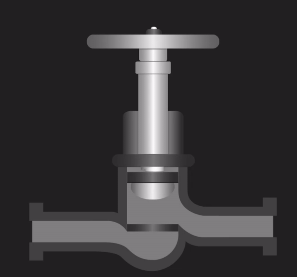
Globe valves are one of the most common valves in every industry because of their ability to start, stop, and throttle fluid flow. Generally, they consist of a movable disk/plug and a stationary ring seat, which is in a spherical body. The valve seat is in the middle of the pipe cross-section, with its aperture parallel to the pipe.
When actuating the valve, fully lowering the disc shuts off the valve, while fully raising the disc allows flow at its maximum rate. Any position in-between regulates flow in proportion to the vertical travel of the disc, which makes globe valves ideal for throttling. This setup results in a change in the direction of flow across the valve, which is largely responsible for pressure losses in a globe valve.
In this article, we review what dictates flow direction, the flow characteristics of a globe valve, and its CV values.
How to Dictate Flow Direction in a Globe Valve
Because of its importance, there is always an indication on a globe valve from its manufacturer, showing the flow direction. The direction of flow is dependent on whether its design is a flow to open or a flow to close.
Flow to Open
This is also called standard or forward flow because it is the most common flow direction for globe valves. In this setup, the fluid comes into the valve from under the disc. So it tends to lift it upwards, thus, opening the valve. As a result, this flow direction requires higher closing torque and less opening torque, making it ideal for low-pressure applications. When deploying this system in low-temperature applications, it promotes smooth operation, helps protect the packing, and minimizes erosive action on the disc and seat surfaces. Also, this flow direction helps the disc to fit properly on the seat as the valve closes. This ultimately makes the valve less prone to seat leakage.
Flow to Close
Flow to close, which is also referred to as reverse flow, is the less popular flow direction when using a globe valve. In this setup, the fluid comes into the valve from over the disc, which results in a closing action. This flow direction is ideal for high-pressure and high-temperature applications. For high-pressure applications, it helps in maintaining seat sealing and avoiding leakages. The flow direction means the closing torque is less than the opening torque during valve actuation. While in high-temperature service, this configuration ensures that flow diffuses rather than concentrating on the face of the disc. Thereby, it avoids contraction of the stem during cooling. This process tends to lift the disk off the seat, causing leaks. A potential disadvantage of this flow direction is a reduction in the flow capacity of the globe valve.
Flow Characteristics
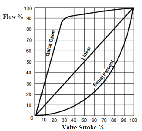
Flow characteristics of any valve refer to the relationship between the flow of the medium and the opening/closing of the valve. When discussing flow characteristics due to only the valve, they are referred to as inherent flow characteristics. But in practice, the entire system flow characteristics include both the valve and pipeline effects and are known as the installed characteristics. Note the inherent characteristics are only valid as long as the pressure difference between the two ends remains constant. For a globe valve, the shape of the disc or plug head determines the inherent flow characteristics. Types include linear, equal percentage, and quick opening.
- Linear: A linear valve flow characteristic means that there is an equal change in flow per unit of valve stroke, irrespective of the disc/plug position.
- Equal Percentage: A valve with equal percentage characteristics suggests that a change in flow per unit of valve stroke is directly proportional to the flow occurring just before the change is made. In other words, the relationship between flow and valve stroke is logarithmic. This characteristic is common in process control.
- Quick Opening: This characteristic allows valve designs to reach maximum flow quickly, so a small valve stroke has a larger flow increase. Using quick open plugs is ideal for on-off applications.
Globe Valve CV Values
The Cv value of a globe valve relates the valve’s flow rate in gallons per minute (gpm) to pressure drop in psi at a temperature of 60℉. So, the larger the Cv value, the greater the flow rate from the valve. For flow through a globe valve, the Cv values vary significantly depending on the bore pattern of the valve. Although manufacturers can customize bore patterns to suit unique project specifications, there are three predominant patterns.
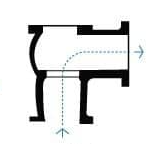
Z-shaped/T Pattern
This is the most common pattern for water applications. The valve seat is horizontal, thus, allowing the stem and disk to travel at right angles to the pipe axis. This gives the globe valve good throttling and sealing ability. However, the Cv values associated with this pattern are low as the pressure drop across the valve is high. This is largely because the flow has to make two 90° turns between the valve inlet and outlet, similar to a “Z” shape.

Flow Path, Courtesy: SAVREE
Angle Pattern
The angle pattern enables the globe valve to act as both a valve and a 90° elbow. Because the change in flow direction across the valve is only 90°, there is less pressure drop and higher Cv values compared to the Z-shaped globe valve.
Courtesy: SAVREE
Y Pattern
The Y-pattern has its seat and stems at approximately 45° to the inlet and outlet pipes. Thus, it provides a much straighter flow path than in other patterns.
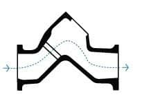
Courtesy: SAVREE
This design remedies the high-pressure drop that is common in globe valves and yields the highest CV values, as the table below shows.
| Valve Size (inches) | Z-Pattern | Angle Pattern | Y-Pattern |
| 1/4 | – | 1.10 | 2.90 |
| 3/8 | – | 1.40 | 3.80 |
| 1/2 | 1.00 | 2.60 | 3.50 |
| 3/4 | 2.80 | 5.60 | 9.00 |
| 1 | 5.80 | 9.90 | 15.00 |
| 1¼ | 10.00 | 13.00 | 22.00 |
| 1½ | 13.30 | 23.30 | 45.00 |
| 2 | 24.00 | 39.70 | 75.00 |
Recent Comments