API 6D is the American Petroleum Institute’s specification for pipeline and pipeline valves in the petroleum and natural gas industries. It contains requirements for the design, manufacture, assembly, documentation, and testing of ball, gate, plug, and check valves for pressure ratings up to ASME class 2500. In this article, we will review what constitutes an API 6D ball, gate, plug, and check valve, design considerations, as well as API 6D vs API 598.
API 6D Ball Valve
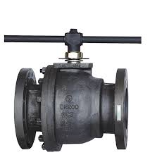
API 6D ball valves are ideal for shutoff applications in the petrochemical, power, and oil & gas industries. Their design delivers high performance and reliability over extended periods. For API 6D, ball valves are available for only the following pressure ratings: class 150, class 300, class 600, class 900, class 1500, and class 2500.
Sizes range from NPS 2 to 36 inches or DN 50 to 900 mm in both full bore and reduced bore. The standard specifies that the obturator of the valve shall rotate on an axis perpendicular to the direction of flow. Also, the wrench and/or the position indicator shall be either in line or transverse with the pipeline when the valve is open and closed respectively. Importantly, the design of this indicator shall not permit assembly in a way that it falsely interprets the valve position. Typical configurations of ball valves from the API 6D are top-entry, three-piece, and welded body ball valves.
API 6D Check Valve
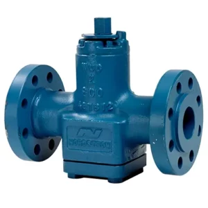
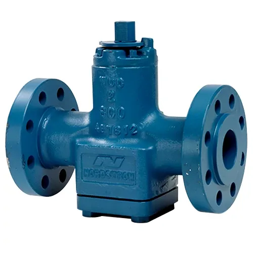
API 6D check valves are full port swing check valves that primarily serve in industrial facilities to prevent backflow. Also, their closure makes them easy to troubleshoot and maintain, with top-entry access to all valve internals. When fully open, the closure mechanism must fully clear the path of flow. There are different types including wafer, axial flow, and lift type either with full or reduced-opening configuration. API 6D check valves are available for the same pressure ratings as the ball valves, but their size range is smaller, spanning from NPS 2 to 24 inches or DN 50 to 600 mm.
The standard recommends check valves as a secondary means of isolation at injection points for sealant, lubrication or flushing. When used in this capacity, they shall be rated higher than the pipeline and injection pressure. Any locking position of check valves shall be in the open position only and the position of its obturator should not be influenced by the flow’s dynamic forces.
Also, API 6D check valves are to have a clear marking of the flow direction on its body. The supplier should ensure the disc is secure during shipping. Prior to pigging, operators must ensure the valve can accept such an operation.
API 6D Gate Valve
Generally, API 6D gate valves come as a single-piece or multi-piece construction for slab-gate valves and expanding-gate valves respectively. In addition to the primary stem sealing, they are to come with a secondary sealing feature in the form of a back seat.
API 6D specifies that the design of gate valves shall be such that forces generated from internal pressure shall not alter the position of the obturator. The standard also recommends shipping of reverse-acting through-conduit gate valves in the open position, unless fitted with a fail-to-close actuator. As for other types of gate valves, shipping shall be in the full-closed position.
API 6D Plug Valve
According to API 6D, plug valves shall have a conical or cylindrical obturator that rotates on an axis perpendicular to the flow direction. It is available in the usual size range of NPS 2 to NPS 36, but most larger sizes are limited to the venturi configuration.
For plug valves, the standard specifies that the wrench or position indicator shall be in line with the pipeline when the valve is open. But when the valve is closed, it shall be transverse. In addition, its design shall be such that the components of the indicator/wrench cannot be assembled to falsely indicate the valve position. Valves without position stops shall make provision for the verification of open and closed alignment with the actuator removed. During hydrostatic and low-pressure gas seat tests, leakage for lubricated plug valves shall not exceed ISO 5208 Rate A (no visible leakage).
API 6D Valve Design
Beyond specifications for individual valves, API 6D has general recommendations covering various aspects of valve design. Some of them include lifting, allowable stress and deflections, as well as material specifications.
Lifting of Valves
The standard specifies that valves of NPS 8 or larger shall have lifting points. It is the responsibility of the manufacturer to verify the suitability of these lifting points for the complete valve and operator assembly. But, if the purchaser is responsible for the supply of the operator assembly, then the purchaser shall provide adequate information to enable the manufacturer to verify the suitability.
Allowable Stress and Deflection
To minimize the risk of failure, API 6D recommends allowable stresses and deflections for the drive train components of valves. Some of them are as follows:
-
- The design of the drivetrain shall place its weakest component outside the pressure boundary.
-
- When delivering the design thrust or torque, the tensile stresses in drivetrain components and stem extensions shall not exceed 67% of SMYS. Also, shear, torsion, and bearing stresses shall not exceed limits specified in ASME Code Section VIII, Division 2, Part AD-132. These limits do not include proprietary bearings or other components with high bearing strength capacity.
-
- A strength efficiency factor of 0.75 shall be used for fillet welds.
-
- Deflections of the drivetrain shall not prevent the obturator from reaching the fully open or fully closed position.
-
- The manufacturer shall demonstrate by testing or calculation that external loads or loads from design pressure do not impair sealing or functionality. Because allowable stress and deflection limits of design codes alone might not result in valve functionality.
Materials
Some of the specifications of API 6D valve materials are as follows:
-
- Pressure-retaining parts shall be made of materials consistent with the pressure-temperature rating.
-
- All process-wetted parts and lubricants shall be compatible with the commissioning and service fluids specified by the purchaser.
-
- Selection of elastomeric materials for hydrocarbon gas service at pressures of PN 100 (class 600) and above shall consider the effect of explosive decompression.
-
- As for metallic parts, material selection shall be geared to avoid corrosion and galling. Forged materials shall be hot worked and heat treated to produce uniform grain size and mechanical properties in the finished product.
-
- For sour service specifications, materials for pressure-containing, pressure-controlling parts, and bolting shall meet the requirements of ISO 15156 (all parts).
API 6D vs API 598
Although API 6D and API 598 are from the same institute and both apply to valves, several differences between them exist as the following table highlights.
| Differences | API 6D | API 598 |
| Purpose | Provides specifications for pipeline valves, especially those in the petroleum and natural gas industry. | Covers inspection, examination, and pressure testing of valves in general. |
| Industry Application | Stringent standards for examination and testing of pipeline valves. Also includes longer pressure times, more test items, and sophisticated operating methods. | Common testing regulations for valves designed with API 602, API 608, and API 609. |
| Valve Coverage | Gate, ball, plug, and check valves. | Globe, gate, plug, ball, check, and butterfly valves. |
| Test Coverage | Includes tests such as stem backseat test, hydrostatic shell test, hydrostatic seat test. | Covers closure examinations, shell examinations, backseat examinations |
| Test Duration | Generally provides longer test times as follows: backseat test (120-300s), shell test (120-1,800s), and seat test (120-300s). | Test duration is directly proportional to valve size, but shorter test times than API6D. Range for each test is as follows: shell (15-300s), backseat (15-60s), closure for check valves (60-120s), and other closure tests (15-120s) |
| Test Medium | For hydrostatic shell and backseat tests, the medium is freshwater with a corrosion inhibitor. If it is a low-pressure closure test, the medium is air or nitrogen. While high-pressure closure tests use freshwater or inert gas. | When doing hydrostatic shell and backseat examinations, the medium is air, inert gas, water, kerosene, or non-corrosive fluid. Then, air or inert gas serves for low-pressure closure tests. Whereas air, inert gas, water, kerosene, or non-corrosive fluid serve for high-pressure closure tests. |
Recent Comments