A gate valve is typically used in industrial settings to completely restrict flow, or to fully allow flow when it is in the open position. It achieves this by lowering or raising its obturator from the seating surface. As a result, it usually occupies more space than most types of valves and is not ideal for flow regulation. In this article, we review common gate valve components, the gate valve assembly, and common problems.
Common Gate Valve Components
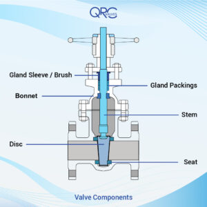
The primary components of a gate valve include the body, bonnet, gate, stem, and seat.
Body
This is the main pressure-retaining part of the valve and contains other operational parts such as the gate and seat. Moreover, it provides passage to flow from the valve and is connected to the piping on both ends. A variety of connections including threaded, flange, butt weld, compression fitting, and tube fitting can serve in connecting the body to the piping. Selecting the best connection type is key and is determined by client’s specifications, valve size, and operating pressure.
Bonnet
The bonnet provides another pressure-retaining part that encloses and protects a gate valve’s stem and wedge. Generally, connects and disconnects from the body to provide access for the repair or maintenance of internal components. Common body-bonnet connections include:
- Screwed Bonnet: This simple body-bonnet connection offers quick access into the valve. However, they are limited to small size gate valves and low-pressure applications. When used in these applications, screwed bonnets can deliver a long-lasting, leak-proof seal and easy disassembly.
- Union Bonnet: In this design, a union nut rests on the lower edge of the bonnet, and screws into the threads of the valve body. As a result, it prevents the leak-proof seal from deteriorating over time. This more robust connection provides a better option than the screwed bonnet when operators require frequent bonnet removal.
- Bolted Bonnet: As valve sizes get larger and the working pressure increases, using flanges and bolts becomes necessary. This robust connection requires a gasket to seal the body-bonnet joint.
- Welded Bonnet: This option works well for designs where the operator does not require the disassembly of the body bonnet. It offers a much lighter assembly than the bolted bonnet and operates in the same pressure range.
- Pressure Seal Bonnet: A pressure seal bonnet is specifically for high-pressure applications in excess of 1,500 psi (103 bar). It has a unique mechanism where the operation pressure helps to improve the body-bonnet joint seal as the internal pressure increases. Typically, it is used alongside bolts and flanges.
Gate
The gate, sometimes referred to as a disc or obturator, moves to either obstruct or allow flow through the valve. There are several types of gate designs and technologies depending on the application’s requirements. Design types include:
- Wedge gate: This common gate utilizes a wedge-shaped disc, which sits or rises from two inclined seats to obstruct or allow flow respectively. It is ideal for applications where there is high flow or turbulence such as steam service.
Because of its shape, frictional seat wear is minimal rubs and thus sticks under high differential pressures. As a result, it lasts longer than most other types of gates. In the case of high temperature, a flexible wedge gate provides a better option than a solid gate and prevents thermal locking as well.
- Slab gate: The slab gate provides a through-conduit gate and derives its name from its design. It is a single-piece gate containing a bore-size hole that aligns to the pipe bore when in the open position.
As a result, it provides a smooth turbulence-free flow, making it ideal for systems that require minimum pressure loss. Although the valve seat often remains debris free, the disc cavity is prone to catching foreign materials. Thus, slab gates usually include a plug to remove these materials during maintenance.
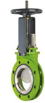
- Knife gate: Whenever flow contains plastic solids and high-viscosity slurries such as paper pulp, a knife gate provide an effective option. The knife gate enables it to cut through these materials and stop the flow.
- Parallel Slide gate: The parallel slide gate works well in high-pressure and temperature applications in which with their internal springs feature located between both discs, helps the disc to be in contact with the seat rings and prevent thermal expansion.
This design requires an equalizing system to operate correctly. This equalizing system could require adding a vent hole on either side of the disc, but this vent hole will only allow the valve to work in unidirectional use. Another option involves adding an external bypass arrangement to operate the valve in a bi-directional flow.
Seat
A gate valve has two seats that interface with the gate to ensure the sealing of the valve. These seats come either as part of the body or in a seat ring construction. When the seat is part of the body, then they are both made of the same material. Whereas in a ring construction, the seats threads or presses into position before welding onto the valve body. This method allows for more variation than in integral seats, and provides the preferred method in high-temperature applications.
Stem
The stem’s forged shaft transfers motion from the actuator to the gate when closing or opening the valve. A gate valve uses either a rising or non-rising stem.
- Rising stem: A rising stem connects directly to the gate and rises when opening the valve, and lowers when the valve is closing. As a result, they contain built-in visual indicators and are easy to lubricate due to their exposed threading.
However, they contact the flow medium, increasing threading corrosion and debris carryover risk. Also, due to the motion of the stem, they are not suitable for use with bevel gears or automatic actuation.
- Non-rising stem: For a non-rising stem, the disc threads internally to the stem, so it moves up and down the stem for opening and closing. This makes it ideal for applications with space limitations, automatic actuation, and corrosive media.
Gate Valve Assembly
A gate valve assembly includes the valve mechanism and peripheral devices involved in the functioning of a valve. An important aspect of the assembly is the actuation method used in opening and closing the valve.
- Manual actuation: This method uses the rotation of a handwheel that is linked to the stem to open and close the gate valve. It is the most economical actuation method, but requires a user on-site to operate the valve. Most times this is not a problem because after installation, the frequency of operation of gate valves is typically low.
- Pneumatic actuation: Rather than using a handwheel, pneumatic actuation provides compressed air to spin the stem. This allows for the remote operation of the valve.
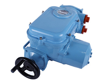
- Electric actuation: An electric motor can also deliver the needed rotation to the stem instead of a handwheel. Similar to pneumatic actuation, this also allows for remote operation of gate valve components, but using an electric source of power.
Installing Gate Valve Components
When installing a gate valve assembly, there are some important tips to follow to ensure the components are safe and functional. Some of these include:
- Inspect components such as the gate, seat, and valve material to ensure there are no defects prior to installation.
- Ensure that welding work is complete and the weld area contains no residue and other debris. Also, check that the flanges have cooled to ambient temperature before installation using the appropriate gaskets.
- In addition, there should be no warpage or misalignment between the flange and gate valve. If the valve is large, there may be a need for some structural support to reduce the load on the pipe assembly.
- Adjust the two flanges to allow for enough space to slip the valve in or out for service, then carefully install the spacing bolts. This should be done in a way that the bottom of the valve rests on the bolts to prevent the valve from falling through.
- Tighten the bolts in stages so an even pressure and a proper seal exists between the flanges, valve, and gasket.
- Finally, lubricate and operate the valve several times and check the stability of the assembly.
Common Problems with Gate Valves
Like other valves, gate valves may encounter issues during operation:
- In rising stem gate valves, the stem thread is exposed to the flow medium which could lead to corrosion. Also, some dirt from the flow could find its way into the threading. Thus, difficulty in properly opening or closing may occur. A partially open gate valve introduces turbulence and frictional losses to the flow.
- Also, with the intrusion of debris into the stem thread and other moving parts, wear and eventually leakages from the valve may occur.
- Another common problem with gate valves is leakage from the flange joint, especially when not properly installed. Manually actuated gate valves are usually heavy and require additional support. Otherwise, excessive loading of the piping assembly may cause leakage from the valve-flange joint.
Recent Comments